
Almost everything written about battery-free sensing assumes a retrofit: you have an asset in the field, you attach a tag, you read it. That is the easy case, and we have covered it elsewhere. If that is where you are, start with the practical filter and the per-technology pages for UHF RFID, Bluetooth and NFC.
Designing the sensor into the product at the manufacturing stage is a different problem. The sensor’s radio environment is no longer something you find; it is something you build. And by the time the enclosure drawing is frozen, most of the decisions that determine whether the sensor works have already been made, usually by people who did not know they were making RF decisions. This post is the checklist we would want on the table before that freeze.
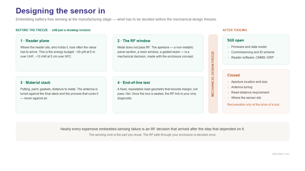
What actually changes when the sensor is designed in
In a retrofit you keep three freedoms: you choose where the tag goes, you can move it if the read is weak, and you can reach it again. Designed-in, you lose all three at once. Position is fixed by the mechanical design, the tag spends the life of the asset inside a material stack that will never be re-tuned, and nobody is opening a sealed medium-voltage compartment to adjust an antenna.
In exchange you get the thing retrofit can never give you: measurement from inside. Contact temperature on a busbar joint rather than air temperature near it; pressure inside the gas compartment rather than at a gauge; strain in the part rather than on its surface. That is the whole reason to embed, and it is why the engineering has to be right the first time.
Decide the reader plane before you decide anything else
A battery-free sensor does not have a range; it has a link. UHF harvesting gives you on the order of 30 µW at 5 m from a standard 2 W ERP reader. NFC gives you roughly 10 mW (three orders of magnitude more) but only at a few centimetres. Which of those budgets you can afford dictates the protocol, the antenna, the aperture and, in practice, what you are able to measure and how often.
So the first question is not “which sensor?”. It is: where will the reader be, who is holding it, and how often does the value need to arrive? A fixed portal in the factory, a handheld on a quarterly inspection round, a phone tapped on the panel door by a technician who already had to walk there. Those are three different products. Pick one before the mechanical concept exists, not after.
The expensive version of this mistake is familiar: the enclosure is tooled, and only then does someone ask for a 5 m read through a steel door.
The RF window is a mechanical decision
Metal enclosures do not pass RF, and battery-free does not repeal physics. If the sensor is inside metal, the field needs a way in and out: a non-metallic panel section, a resin-filled window, a viewport, a gasketed seam, a cable gland.
What matters is the size of that opening relative to the wavelength, and the geometry matters as much as the area. A slot is far better than a round hole of the same area, and it works best when its long dimension approaches a half wavelength — roughly 16 cm at UHF. Below that, transmission through a thin panel falls away very steeply as the opening shrinks; and if the opening has depth — a gland, a deep recess — it behaves like a waveguide below cutoff and attenuates exponentially with that depth. So the aperture is not a yes/no. It is a term in your link budget, and usually the largest one.
This is a different question from the size of the tag. A printed UHF dipole comes out well under a free-space half wave — our evaluation tags are around 136 mm — because the substrate and the conjugate match to the chip shorten it electrically. A small antenna is routine. A small aperture is expensive.
Near-field NFC is a different regime altogether: it couples through a much smaller non-metallic window, but only at centimetre range.
The practical test is blunt: if your mechanical engineer can point at the place where the field gets in and out, and that place is not going to be redesigned next month, you have a project. If nobody can point at it, that is the first thing to fix, before anyone specifies a sensor.
Tune the antenna against the final material stack, not against air
Potting compound, epoxy, paint, gaskets, the insulator body, the distance to the busbar it is clamped to: every one of them moves resonance and loads Q. An antenna tuned on the bench and then potted can lose most of its harvested power, and there is no firmware fix for a detuned antenna.
What the RF team needs, early, is the real stack: materials, thicknesses, dielectric constants where they are known, and the mounting distance to metal. If those are still open, that is not a detail to resolve later: it is a schedule risk you should be tracking. Metal-mount antennas exist and work, but they buy immunity with efficiency; budget for that cost deliberately instead of discovering it in the first prototype.
The sensor has to survive your process, not just your product
Embedded parts go through the factory. Reflow, potting cure and its exotherm, paint bake, vacuum or pressure steps, cleaning, and (in high-voltage equipment) the routine dielectric withstand and partial-discharge tests. Each one deserves two separate questions, and teams routinely only ask the first:
- Does it survive? Our sensing parts operate across a −40 to +85 °C range, but a cure exotherm or a reflow profile is a different question from ambient operation.
- Does it still read afterwards? A process step that changes the dielectric around the antenna changes its tuning. Surviving and working are not the same result.
Then there is the lifecycle. High-voltage assets are specified for decades, and matching that lifetime is most of the argument for going battery-free in the first place, but only if the encapsulation and the mount last as long as the silicon does.
Plan how you will test it once the box is closed
This is the most underrated item on the list. After the enclosure is sealed, the RF link is your only diagnostic.
Two things to design in before pre-series:
- An end-of-line read at a fixed, repeatable geometry that records margin, not pass/fail. A tag that reads at 10 cm on the production line but needs 3 m in the field has already failed; a binary test just will not tell you until the units are installed.
- A way to distinguish “weak field” from “broken sensor” in the field. Without it, every marginal read turns into a truck roll and an argument. This is exactly what the QoS byte in our senseRead line reports: the quality of the RF power the tag is receiving, alongside the measurement itself.
And decide the commissioning scheme while you are at it: which ID goes into the part, at what point it gets associated with the asset serial number, and where that mapping lives. Retrofitting an identity scheme onto units already in the field is miserable work.
The sequence that actually works
The order matters more than any individual decision. Each of these has to land before the step that depends on it:
- Reader plane and read frequency, before the enclosure concept.
- Protocol and measurement requirement, before the enclosure concept.
- Aperture location and material, with the enclosure concept, not after it.
- Material stack and mounting definition, before antenna design.
- Antenna design and tuning against that stack, before tooling.
- Process-survival trials on the real stack, before pre-series.
- End-of-line test fixture and margin criterion, before pre-series.
- Commissioning and ID scheme, before pre-series.
Nearly every expensive embedded-sensing failure we have seen is one of steps 3, 4 or 7 arriving after the step that needed it.
What we cannot fix downstream
Being honest about the limits is cheaper for everyone than being optimistic:
- A fully sealed metal enclosure with no aperture and no willingness to add one. There is no clever antenna that solves this.
- A read-distance requirement that appears after the tooling is cut. Sometimes recoverable, never cheap.
- An unknown or highly variable reader position combined with a tight energy budget. If we cannot bound where the reader will be, we cannot promise the link.
We would rather say that in week two than in month nine.
If you are at the enclosure-concept stage, a paid scoping study is the cheap way to find out which of these constraints your current design already violates, and what the aperture, stack and test plan need to look like before anything is tooled (while changing them still costs a drawing revision instead of a tool). Talk to us about embedding sensing in your product → And if you would rather see the sensors work first, the eval kits and KL-OSIRIS are the fastest way in.
Next week: maintenance rounds with SenseNFC — tap your phone, read the sensor.